DC Generators
DC GENERATOR THEORY
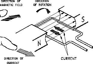
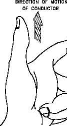
Figure 4 Left-Hand Rule for Generators
Commutator Action
The commutator converts the AC
Figure 5 Commutator Segments and Brushes
voltage generated in the rotating
loop into a DC voltage. It also
serves as a means of connecting
the brushes to the rotating loop.
The purpose of the brushes is to
connect the generated voltage to
an external circuit. In order to do
this, each brush must make contact
with one of the ends of the loop.
Since the loop or armature rotates,
a direct connection is impractical.
Instead, the brushes are connected
to the ends of the loop through the
commutator.
In a simple one-loop generator, the commutator is made up of two semicylindrical pieces of a
smooth conducting material, usually copper, separated by an insulating material, as shown in
Figure 5. Each half of the commutator segments is permanently attached to one end of the
rotating loop, and the commutator rotates with the loop. The brushes, usually made of carbon,
rest against the commutator and slide along the commutator as it rotates. This is the means by
which the brushes make contact with each end of the loop.
Rev. 0
Page 7
ES-05