IMPEDANCE
Basic AC Reactive Components
where
Z = impedance (W)
R = resistance (W)
X = net reactance (W)
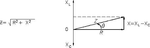
The relationship between resistance, reactance, and impedance is shown in Figure 5.
Figure 5 Relationship Between Resistance, Reactance, and Impedance
The current through a certain resistance is always in phase with the applied voltage. Resistance
is shown on the zero axis. The current through an inductor lags applied voltage by 90°; inductive
reactance is shown along the 90° axis. Current through a capacitor leads applied voltage by 90°;
capacitive reactance is shown along the -90° axis. Net reactance in an AC circuit is the
difference between inductive and capacitive reactance. Equation (8-7) is the mathematical
representation for the calculation of net reactance when XL is greater than XC.
X = XL - XC
(8-7)
where
X = net reactance (W)
XL = inductive reactance (W)
XC = capacitive reactance (W)
ES-08
Page 10
Rev. 0