PRESSURE DETECTION CIRCUITRY
Pressure Detectors
An increase in pressure at the inlet of the bellows causes the bellows to expand. The expansion
of the bellows moves a flexible beam to which a strain gauge has been attached. The movement
of the beam causes the resistance of the strain gauge to change. The temperature compensating
gauge compensates for the heat produced by current flowing through the fine wire of the strain
gauge. Strain gauges, which are nothing more than resistors, are used with bridge circuits as
shown in Figure 5.
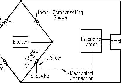
Figure 5 Strain Gauge Used in a Bridge Circuit
Alternating current is provided by an exciter that is used in place of a battery to eliminate the
need for a galvanometer. When a change in resistance in the strain gauge causes an unbalanced
condition, an error signal enters the amplifier and actuates the balancing motor. The balancing
motor moves the slider along the slidewire, restoring the bridge to a balanced condition. The
slider’s position is noted on a scale marked in units of pressure.
IC-02
Page 8
Rev. 0