Radiation Detectors
CIRCUITRY AND CIRCUIT ELEMENTS
Discriminator Circuit
A discriminator circuit selects the minimum pulse height. When the input pulse exceeds
the discriminator preset level, the discriminator generates an output pulse.
The
discriminator input is normally an amplified and shaped detector signal. This signal is
an analog signal because the amplitude is proportional to the energy of the incident
particle.
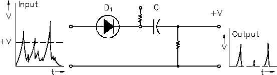
The biased diode circuit is the simplest form of discriminator. Figure 32 shows a biased
diode discriminator circuit with its associated input and output signals.
Figure 32 Biased Diode Discriminator
Diode D1 is shown with its cathode connected to a positive voltage source +V. A diode
cannot conduct unless the voltage across the anode is positive with respect to the cathode.
As long as the voltage at the anode is less than that of the cathode, diode D1 does not
conduct, and there is no output. At some point, anode voltage exceeds the bias value +V,
and the diode conducts. The input signal is allowed to pass to the output.
Figure 32 illustrates input and output signals and how the discriminator acts to eliminate
all pulses that are below the preset level. The output pulses of this circuit have the same
relative amplitudes as the input pulses.
Rev. 0
Page 59
IC-06