DOE-HDBK-1016/1-93
ELECTRICAL DIAGRAMS AND SCHEMATICS
Electrical Diagrams and Schematics
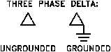
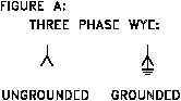
depicting three-phase systems, a small symbol may be placed to the side of the transformer
primary and secondary to indicate the type of transformer windings that are used.
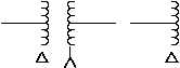
Figure 16 (A) shows the most commonly used symbols to indicate how the phases are connected
in three-phase windings. Figure 16 (B) illustrates examples of how these symbols appear in a
three-phase single line diagram.
Figure 16 Three-Phase Symbols
PR-03
Rev. 0
Page 16