VOLTAGE REGULATORS
Voltage Regulators
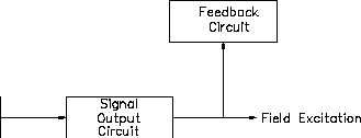
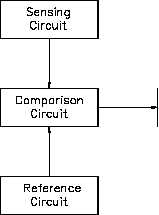
Figure 1 Voltage Regulator Block Diagram
Sensing Circuit
The sensing circuit senses output voltage of the AC generator. As the generator is loaded or
unloaded, the output voltage changes, and the sensing circuit provides a signal of these voltage
changes. This signal is proportional to output voltage and is sent to the comparison circuit.
Reference Circuit
The reference circuit maintains a constant output for reference. This reference is the desired
voltage output of the AC generator.
Comparison Circuit
The comparison circuit electrically compares the reference voltage to the sensed voltage and
provides an error signal. This error signal represents an increase or decrease in output voltage.
The signal is sent to the amplification circuit.
Amplification Circuit
The amplification circuit, which can be a magnetic amplifier or transistor amplifier, takes the
signal from the comparison circuit and amplifies the milliamp input to an amp output, which is
then sent to the signal output, or field, circuit.
ES-11
Page 2
Rev. 0


