Engineering Fluid Diagrams and Prints
DOE-HDBK-1016/1-93
FLUID POWER P&IDs
Valves
Valves are the most complicated symbols in fluid power systems. Valves provide the control that
is required to ensure that the motive media is routed to the correct point when needed. Fluid
power system diagrams require much more complex valve symbology than standard P&IDs due
to the complicated valving used in fluid power systems. In a typical P&ID, a valve opens, closes,
or throttles the process fluid, but is rarely required to route the process fluid in any complex
manner (three- and four-way valves being the common exceptions). In fluid power systems it
is common for a valve to have three to eight pipes attached to the valve body, with the valve
being capable of routing the fluid, or several separate fluids, in any number of combinations of
input and output flowpaths.
The symbols used to represent fluid power valves must contain much more information than the
standard P&ID valve symbology. To meet this need, the valve symbology shown in the
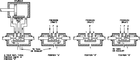
following figures was developed for fluid power P&IDs. Figure 24, a cutaway view, provides
an example of the internal complexity of a simple fluid power type valve. Figure 24 illustrates
a four-way/three-position valve and how it operates to vary the flow of the fluid. Note that in
Figure 24 the operator of the valve is not identified, but like a standard process fluid valve the
valve could be operated by a diaphragm, motor, hydraulic, solenoid, or manual operator. Fluid
power valves, when electrically operated by a solenoid, are drawn in the de-energized position.
Energizing the solenoid will cause the valve to shift to the other port. If the valve is operated
by other than a solenoid or is a multiport valve, the information necessary to determine how the
valve operates will be provided on each drawing or on its accompanying legend print.
Figure 24 Valve Operation
Rev. 0
PR-02
Page 27


