SECOND LAW OF THERMODYNAMICS
Thermodynamics
Power Plant Components
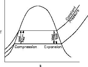
Figure 24 Expansion and Compression Processes
on T-s Diagram
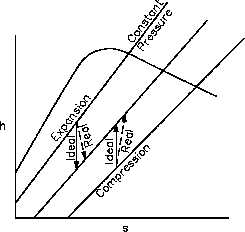
Figure 25 Expansion and Compression Processes
on h-s Diagram
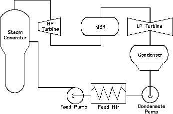
In order to analyze a complete power plant steam power cycle, it is first necessary to analyze the
elements which make up such cycles. (See Figure 26) Although specific designs differ, there are
three basic types of elements in power cycles, (1) turbines, (2) pumps and (3) heat exchangers.
Associated with each of these three types of elements is a characteristic change in the properties
of the working fluid.
Previously we have calculated
Figure 26 Steam Cycle
system efficiency by knowing the
temperature of the heat source and
the heat sink. It is also possible to
calculate the efficiencies of each
individual component.
The efficiency of each type of
component can be calculated by
comparing
the
actual
work
produced by the component to the
work that would have been
produced by an ideal component
operating isentropically between
the
same
inlet
and
outlet
conditions.
HT-01
Page 78
Rev. 0