INTRODUCTION TO THE TYPES
DOE-HDBK-1016/1-93
Introduction to Print Reading
OF DRAWINGS, VIEWS, AND PERSPECTIVES
Drawing Format
P&IDs, fabrication, construction, and architectural drawings can be presented using one of several
different formats. The standard formats are single line, pictorial or double line, and cutaway.
Each format provides specific information about a component or system.
Single Line Drawings
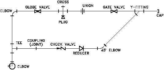
The single line format is most commonly used in P&IDs. Figure 12 is an example of a
single line P&ID. The single line format represents all piping, regardless of size, as
single line. All system equipment is represented by simple standard symbols (covered in
later modules). By simplifying piping and equipment, single lines allow the system's
equipment and instrumentation relationships to be clearly understood by the reader.
Pictorial or Double Line Drawings
Figure 12 Example of a Single Line P&ID
Pictorial or double line drawings present the same type information as a single line, but
the equipment is represented as if it had been photographed. Figure 13 provides an
example illustration of a pictorial drawing. This format is rarely used since it requires
much more effort to produce than a single line drawing and does not present any more
information as to how the system functions. Compare the pictorial illustration, Figure 13,
to the single line of the same system shown in Figure 12. Pictorial or double line
drawings are often used in advertising and training material.
PR-01
Rev. 0
Page 16


