Introduction To Print Reading
DOE-HDBK-1016/1-93
INTRODUCTION TO THE TYPES
OF DRAWINGS, VIEWS, AND PERSPECTIVES
As a rule P&IDs do not have a drawing scale and present only the relationship or sequence
between components. Just because two pieces of equipment are drawn next to each other does
not indicate that in the plant the equipment is even in the same building; it is just the next part
or piece of the system. These drawings only present information on how a system functions, not
the actual physical relationships.
Because P&IDs provide the most concise format for how a system should function, they are used
extensively in the operation, repair, and modification of the plant.
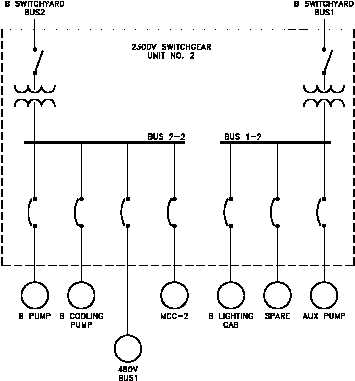
Electrical Single Lines and Schematics
Electrical single lines and
Figure 7 Example of a Single Line
schematics are designed to
present functional information
about the electrical design of a
system or component. They
provide the same types of
information about electrical
systems that P&IDs provide
for piping and instrument
systems.
Like
P&IDs,
electrical prints are not usually
drawn to scale. Examples of
typical single lines are site or
building power distribution,
system power distribution, and
motor
control
centers.
Figure 7 is an example of an
electrical single line.
Electrical schematics provide a
more
detailed
level
of
information about an electrical
system or component than the
single
lines.
Electrical
schematic drawings present
information such as the individual relays, relay contacts, fuses, motors, lights, and instrument
sensors. Examples of typical schematics are valve actuating circuits, motor start circuits, and
breaker circuits.
Rev. 0
PR-01
Page 11