Miscellaneous Mechanical Components
DOE-HDBK-1018/2-93
AIR COMPRESSORS
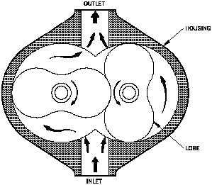
The rotary lobe-type, illustrated in Figure
Figure 4 Rotary Lobe Air Compressor
4, features two mating lobe-type rotors
mounted in a case. The lobes are gear
driven at close clearance, but without
metal-to-metal contact. The suction to the
unit is located where the cavity made by
the lobes is largest. As the lobes rotate,
the cavity size is reduced, causing
compression of the vapor within. The
compression continues until the discharge
port is reached, at which point the vapor
exits the compressor at a higher pressure.
The
rotary
liquid
seal
ring-type,
illustrated in Figure 5, features a forward
inclined, open impeller, in an oblong
cavity filled with liquid. As the impeller
rotates, the centrifugal force causes the
seal liquid to collect at the outer edge of
the oblong cavity. Due to the oblong configuration of the compressor case, large longitudinal
cells are created and reduced to smaller ones. The suction port is positioned where the
longitudinal cells are the largest, and for the discharge port, where they are smallest, thus
causing the vapor within the cell to compress as the rotor rotates. The rotary liquid seal
compressor is frequently used in specialized applications for the compression of extremely
corrosive and exothermic gasses and is commonly used in commercial nuclear plants as a means
of establishing initial condenser vacuum.
Figure 5 Rotary Liquid Seal Ring Air Compressor
Rev. 0
ME-05
Page 5


