MAGNETIC CIRCUITS
Basic Electrical Theory
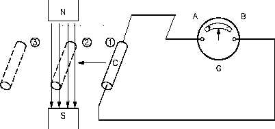
If the conductor is moving outside the magnetic field at position 1, zero EMF is still indicated
by the galvanometer. When the conductor is moved to position 2, the lines of magnetic force
will be cut by the conductor, and the galvanometer will deflect to point A. Moving the
conductor to position 3 will cause the galvanometer to return to zero. By reversing the direction
in which the conductor is moved (3 to 1), the same results are noticed, but of opposite polarity.
If we hold the conductor stationary in the magnetic lines of force, at position 2, the galvanometer
indicates zero. This fact shows that there must be relative motion between the conductor and the
magnetic lines of force in order to induce an EMF.
Figure 29 Induced EMF
The most important application of relative motion is seen in electric generators. In a DC
generator, electromagnets are arranged in a cylindrical housing. Conductors, in the form of coils,
are rotated on a core such that the coils continually cut the magnetic lines of force. The result
is a voltage induced in each of the conductors. These conductors are connected in series, and
the induced voltages are added together to produce the generator’s output voltage.
Faraday’s Law of Induced Voltage
The magnitude of the induced voltage depends on two factors: (1) the number of turns of a coil,
and (2) how fast the conductor cuts across the magnetic lines of force, or flux. Equation (1-20)
is the mathematical representation for Faraday’s Law of Induced Voltage.
Vind
=
(1-20)
N
DF
Dt
where
Vind
= induced voltage, V
ES-01
Page 42
Rev. 0