DC GENERATOR THEORY
DC Generators
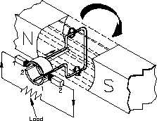
Figure 3 Basic Operation of a DC Generator
A single conductor, shaped in the form of a loop, is positioned between the magnetic poles. As
long as the loop is stationary, the magnetic field has no effect (no relative motion). If we rotate
the loop, the loop cuts through the magnetic field, and an EMF (voltage) is induced into the loop.
When we have relative motion between a magnetic field and a conductor in that magnetic field,
and the direction of rotation is such that the conductor cuts the lines of flux, an EMF is induced
into the conductor. The magnitude of the induced EMF depends on the field strength and the
rate at which the flux lines are cut, as given in equation (5-1). The stronger the field or the more
flux lines cut for a given period of time, the larger the induced EMF.
Eg = KFN
(5-1)
where
Eg = generated voltage
K = fixed constant
F = magnetic flux strength
N = speed in RPM
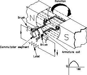
The direction of the induced current flow can be determined using the "left-hand rule" for
generators. This rule states that if you point the index finger of your left hand in the direction
of the magnetic field (from North to South) and point the thumb in the direction of motion of
the conductor, the middle finger will point in the direction of current flow (Figure 4). In the
generator shown in Figure 4, for example, the conductor closest to the N pole is traveling upward
across the field; therefore, the current flow is to the right, lower corner. Applying the left-hand
rule to both sides of the loop will show that current flows in a counter-clockwise direction in the
loop.
ES-05
Page 6
Rev. 0