INDUCTANCE
Basic AC Reactive Components
where
p = ~3.14
f = frequency (Hertz)
L = inductance (Henries)
The magnitude of an induced EMF in a circuit depends on how fast the flux that links the circuit
is changing. In the case of self-induced EMF (such as in a coil), a counter EMF is induced in
the coil due to a change in current and flux in the coil. This CEMF opposes any change in
current, and its value at any time will depend on the rate at which the current and flux are
changing at that time. In a purely inductive circuit, the resistance is negligible in comparison to
the inductive reactance. The voltage applied to the circuit must always be equal and opposite
to the EMF of self-induction.
Voltage and Current Phase Relationships in an Inductive Circuit
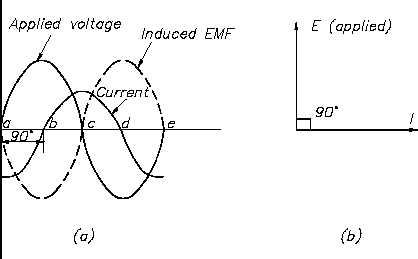
As previously stated, any change in current in a coil (either a rise or a fall) causes a
corresponding change of the magnetic flux around the coil. Because the current changes at its
maximum rate when it is going through its zero value at 90° (point b on Figure 1) and 270°
(point d), the flux change is also the greatest at those times. Consequently, the self-induced EMF
in the coil is at its maximum (or minimum) value at these points, as shown in Figure 1. Because
the current is not changing at the point when it is going through its peak value at 0° (point a),
180° (point c), and 360° (point e), the flux change is zero at those times. Therefore, the self-
induced EMF in the coil is at its zero value at these points.
Figure 1 Current, Self-Induced EMF, and Applied Voltage in an Inductive Circuit
ES-08
Page 2
Rev. 0