Temperature Detectors
TEMPERATURE DETECTION CIRCUITRY
The battery is connected to two opposite points of the bridge circuit. The millivoltmeter is
connected to the two remaining points. The rheostat regulates bridge current. The regulated
current is divided between the branch with the fixed resistor and range resistor R1, and the branch
with the RTD and range resistor R2. As the electrical resistance of the RTD changes, the voltage
at points X and Y changes. The millivoltmeter detects the change in voltage caused by unequal
division of current in the two branches. The meter can be calibrated in units of temperature
because the only changing resistance value is that of the RTD.
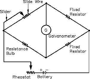
The balanced bridge circuit (Figure 10) uses a galvanometer to compare the RTD resistance with
that of a fixed resistor. The galvanometer uses a pointer that deflects on either side of zero when
the resistance of the arms is not equal. The resistance of the slide wire is adjusted until the
galvanometer indicates zero. The value of the slide resistance is then used to determine the
temperature of the system being monitored.
Figure 10 Balanced Bridge Circuit
A slidewire resistor is used to balance the arms of the bridge. The circuit will be in balance
whenever the value of the slidewire resistance is such that no current flows through the
galvanometer. For each temperature change, there is a new value; therefore, the slider must be
moved to a new position to balance the circuit.
Rev. 0
Page 13
IC-01