Process Controls
CONTROLLERS
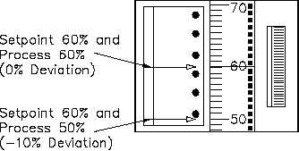
The deviation indicator, located left of the setpoint indicator, displays any error (+10%
to -10%) between setpoint value and actual controlled variable value. With no error, the
deviation pointer stays at mid-scale, in line with the setpoint index mark. If the
controlled variable is lower than setpoint, the deviation indicator deflects downward. If
higher, the indicator deflects upward. An example of this is shown in Figure 33.
Figure 33 Deviation Indicator
The output meter is the horizontally positioned meter below the deviation and setpoint
indicators. It indicates controller output signal in percent. This particular controller
ranges from zero to 100% current. However, this will correspond to an air signal for
pneumatic controllers.
Snap-in tabs, above each end of the output meter, indicate the direction the final control
element moves for a change in the output signal. Tabs normally read "open-close" for
control valves and "slow-fast" for variable-speed motors, or other appropriate
designations.
The manual-automatic (M-A) transfer switch, immediately below the output meter, selects
operating mode of the controller.
A manual output adjust knob, in the center of the M-A transfer switch, varies the
controller output signal in manual mode of operation. The knob is rotated clockwise to
increase the signal and counterclockwise to decrease the signal.
The M-A transfer switch has five positions that alter the mode of operation. The indication is
provided by the deviation meter.
AUTO. This is the normal position of the M-A transfer switch. It places the controller
in the automatic mode of operation. Also, the deviation meter indicates any deviation
between controlled variable and setpoint.
Rev. 0
Page 49
IC-07