DOE-HDBK-1016/1-93
Electrical Diagrams and Schematics
ELECTRICAL DIAGRAMS AND SCHEMATICS
On the primary side of the transformer the dot indicates current in; on the secondary side the dot
indicates current out.
If at a given instant the current is flowing into the transformer at the dotted end of the primary
coil, it will be flowing out of the transformer at the dotted end of the secondary coil. The current
flow for a transformer using the dot symbology is illustrated in Figure 2.
Switches
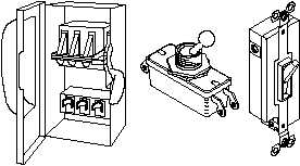
Figure 3 shows the most common types of switches and their symbols. The term "pole," as used
to describe the switches in Figure 3, refers to the number of points at which current can enter
a switch. Single pole and double pole switches are shown, but a switch may have as many poles
as it requires to perform its function. The term "throw" used in Figure 3 refers to the number
of circuits that each pole of a switch can complete or control.
Figure 3 Switches and Switch Symbols
Rev. 0
PR-03
Page 3


