DOE-HDBK-1016/1-93
ELECTRICAL DIAGRAMS AND SCHEMATICS
Electrical Diagrams and Schematics
Symbology
To read and interpret electrical
Figure 1 Basic Transformer Symbols
diagrams and schematics, the
reader must first be well
versed in what the many
symbols represent.
This
chapter discusses the common
symbols used to depict the
many components in electrical
systems. Once mastered, this
knowledge should enable the
reader
to
successfully
understand
most
electrical
diagrams and schematics.
The information that follows
provides details on the basic
symbols used to represent
components
in
electrical
transmission,
switching,
control,
and
protection
diagrams and schematics.
Transformers
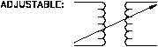
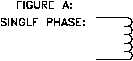
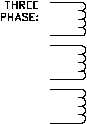
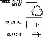
The basic symbols for the
various types of transformers
are shown in Figure 1 (A). Figure 1 (B) shows how the basic symbol for the transformer is
modified to represent specific types and transformer applications.
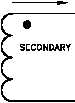
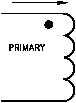
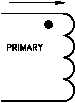
In addition to the transformer
Figure 2 Transformer Polarity
symbol itself, polarity marks
are sometimes used to indicate
current flow in the circuit.
This information can be used
to
determine
the
phase
relationship (polarity) between
the input and output terminals
of a transformer. The marks
usually appear as dots on a
transformer symbol, as shown
in Figure 2.
PR-03
Rev. 0
Page 2