FLUID POWER P&IDs
DOE-HDBK-1016/1-93
Engineering Fluid Diagrams and Prints
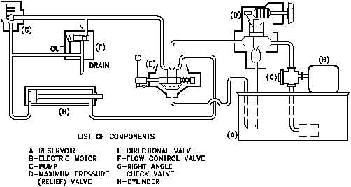
Figure 31 Cutaway Fluid Power Diagram
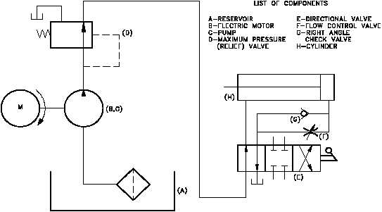
A schematic diagram uses symbols to show the elements in a system. Schematics are designed
to supply the functional information of the system. They do not accurately represent the relative
location of the components. Schematics are useful in maintenance work, and understanding them
is an important part of troubleshooting. Figure 32 is a schematic diagram of the system
illustrated in Figure 30 and Figure 31.
Figure 32 Schematic Fluid Power Diagram
PR-02
Rev. 0
Page 34


