Engineering Fluid Diagrams and Prints
DOE-HDBK-1016/1-93
FLUID POWER P&IDs
Types of Fluid Power Diagrams
Several kinds of diagrams can be used to show how systems work. With an understanding of
how to interpret Figure 29, a reader will be able to interpret all of the diagrams that follow.
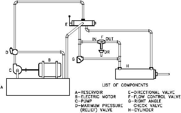
A pictorial diagram shows the physical arrangement of the elements in a system. The
components are outline drawings that show the external shape of each item. Pictorial drawings
do not show the internal function of the elements and are not especially valuable for maintenance
or troubleshooting. Figure 30 shows a pictorial diagram of a system.
A cutaway diagram shows both the physical arrangement and the operation of the different
Figure 30 Pictorial Fluid Power Diagram
components. It is generally used for instructional purposes because it explains the functions
while showing how the system is arranged. Because these diagrams require so much space, they
are not usually used for complicated systems. Figure 31 shows the system represented in
Figure 30 in cutaway diagram format and illustrates the similarities and differences between the
two types of diagrams.
Rev. 0
PR-02
Page 33


