DOE-HDBK-1016/1-93
Engineering Fluid Diagrams and Prints
ENGINEERING FLUIDS DIAGRAMS AND PRINTS
Note that the symbols alone in Figure 3 do not provide the reader with enough information to
determine whether applying air pressure to the diaphragm opens or closes the process control
valve, or whether energizing the solenoid pressurizes or vents the diaphragm. Further, Figure 3
is incomplete in that it does not show the electrical portion of the valve control system nor does
it identify the source of the motive force (compressed air). Although Figure 3 informs the reader
of the types of mechanical components in the control system and how they interconnect, it does
not provide enough information to determine how those components react to a control signal.
Control valves operated by an instrument signal are symbolized in the same manner as those
shown previously, except the output of the controlling instrument goes to the valve actuator.
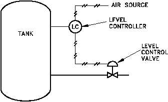
Figure 4 shows a level instrument (designated "LC") that controls the level in the tank by
positioning an air-operated diaphragm control valve. Again, note that Figure 4 does not contain
enough information to enable the reader to determine how the control valve responds to a change
in level.
Figure 4 Level Control Valve
An additional aspect of some control valves is a valve positioner, which allows more precise
control of the valve. This is especially useful when instrument signals are used to control the
valve. An example of a valve positioner is a set of limit switches operated by the motion of the
valve. A positioner is symbolized by a square box on the stem of the control valve actuator. The
positioner may have lines attached for motive force, instrument signals, or both. Figure 5 shows
two examples of valves equipped with positioners. Note that, although these examples are more
detailed than those of Figure 3 and Figure 4, the reader still does not have sufficient information
to fully determine response of the control valve to a change in control signal.
Rev. 0
PR-02
Page 5


