DOE-HDBK-1016/1-93
ENGINEERING FLUIDS DIAGRAMS AND PRINTS
Engineering Fluid Diagrams and Prints
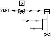
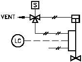
Figure 5 Control Valves with Valve Positioners
In Example A of Figure 5, the reader can reasonably assume that opening of the control valve
is in some way proportional to the level it controls and that the solenoid valve provides an
override of the automatic control signals. However, the reader cannot ascertain whether it opens
or closes the control valve. Also, the reader cannot determine in which direction the valve moves
in response to a change in the control parameter. In Example B of Figure 5, the reader can make
the same general assumptions as in Example A, except the control signal is unknown. Without
additional information, the reader can only assume the air supply provides both the control signal
and motive force for positioning the control valve. Even when valves are equipped with
positioners, the positioner symbol may appear only on detailed system diagrams. Larger, overall
system diagrams usually do not show this much detail and may only show the examples of
Figure 5 as air-operated valves with no special features.
Control Valve Designations
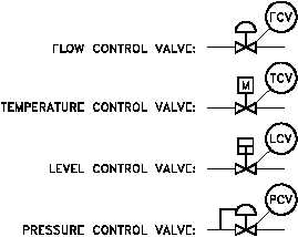
Figure 6 Control Valve Designations
A control valve may serve any number of functions within a fluid system. To differentiate
between valve uses, a balloon labeling system is used to identify the function of a control valve,
as shown in Figure 6. The common convention
is that the first letter used in the valve designator
indicates the parameter to be controlled by the
valve. For example:
F = flow
T = temperature
L = level
P = pressure
H = hand (manually operated valve)
The second letter is usually a "C" and identifies
the valve as a controller, or active component, as
opposed to a hand-operated valve. The third
letter is a "V" to indicate that the piece of
equipment is a valve.
PR-02
Rev. 0
Page 6