DOE-HDBK-1016/1-93
Electrical Diagrams and Schematics
ELECTRICAL DIAGRAMS AND SCHEMATICS
Types of Electrical Diagrams or Schematics
There are three ways to show electrical circuits. They are wiring, schematic, and pictorial
diagrams. The two most commonly used are the wiring diagram and the schematic diagram.
The uses of these two types of diagrams are compared in Table 1.
TABLE 1
Comparison Between Wiring and Schematic Diagrams
Wiring Diagrams
Schematic Diagrams
1.
Emphasize connections between
elements of a circuit or system
2.
Use horizontal and vertical lines to
represent the wires
3.
Use simplified pictorials that clearly
resemble circuit/system components
4.
Place equipment and wiring on
drawing to approximate actual
physical location in real circuit
1.
Emphasize "flow" of system
2.
Use horizontal and vertical lines to
show system flow
3.
Use symbols that indicate function of
equipment, but the symbols do not
look like the actual equipment
4.
Drawing layout is done to show the
"flow" of the system as it functions,
not the physical layout of the
equipment
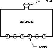
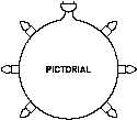
The pictorial diagram is usually
Figure 9 Comparison of an Electrical Schematic
and a Pictorial Diagram
not
found
in
engineering
applications for the reasons shown
in
the
following
example.
Figure 9 provides a simple
example of how a schematic
diagram compares to a pictorial
equivalent. As can be seen, the
pictorial version is not nearly as
useful as the schematic, especially
if you were trying to obtain
enough information to repair a
circuit or determine how it
operates.
Rev. 0
PR-03
Page 9


