DOE-HDBK-1016/1-93
ELECTRICAL DIAGRAMS AND SCHEMATICS
Electrical Diagrams and Schematics
Reading Electrical Diagrams and Schematics
To read electrical system diagrams and schematics properly, the condition or state of each
component must first be understood. For electrical schematics that detail individual relays and
contacts, the components are always shown in the de-energized condition (also called the shelf-
state).
To associate the proper relay with the contact(s) that it operates, each relay is assigned a specific
number and/or letter combination. The number/letter code for each relay is carried by all
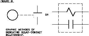
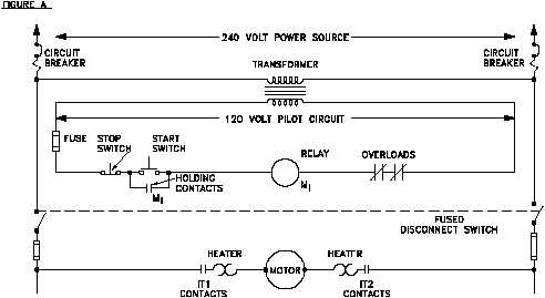
associated contacts. Figure 14 (A) shows a simple schematic containing a coil (M1) and its
contact. If space permits, the relationship may be emphasized by drawing a dashed line
(symbolizing a mechanical connection) between the relay and its contact(s) or a dashed box
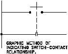
around them as shown in Figure 14 (B). Figure 14 (C) illustrates a switch and a second set of
contacts that are operated by the switch.
Figure 14 Examples of Relays and Relay Contacts
PR-03
Rev. 0
Page 14


