Heat Exchangers
DOE-HDBK-1018/1-93
HEAT EXCHANGER APPLICATIONS
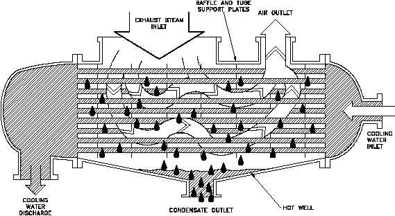
Figure 9 Single-Pass Condenser
There are different condenser designs, but the most common, at least in the large power
generation facilities, is the straight-through, single-pass condenser illustrated Figure 9. This
condenser design provides cooling water flow through straight tubes from the inlet water box
on one end, to the outlet water box on the other end. The cooling water flows once through the
condenser and is termed a single pass. The separation between the water box areas and the
steam condensing area is accomplished by a tube sheet to which the cooling water tubes are
attached. The cooling water tubes are supported within the condenser by the tube support sheets.
Condensers normally have a series of baffles that redirect the steam to minimize direct
impingement on the cooling water tubes. The bottom area of the condenser is the hotwell, as
shown in Figure 9. This is where the condensate collects and the condensate pump takes its
suction. If noncondensable gasses are allowed to build up in the condenser, vacuum will
decrease and the saturation temperature at which the steam will condense increases.
Non-condensable gasses also blanket the tubes of the condenser, thus reducing the heat transfer
surface area of the condenser. This surface area can also be reduced if the condensate level is
allowed to rise over the lower tubes of the condenser. A reduction in the heat transfer surface
has the same effect as a reduction in cooling water flow. If the condenser is operating near its
design capacity, a reduction in the effective surface area results in difficulty maintaining
condenser vacuum.
The temperature and flow rate of the cooling water through the condenser controls the
temperature of the condensate. This in turn controls the saturation pressure (vacuum) of the
condenser.
Rev. 0
ME-02
Page 15