DIESEL ENGINES
DOE-HDBK-1018/1-93
Diesel Engine Fundamentals
Oil is accumulated and stored in the engine's oil pan where one or more oil pumps take
a suction and pump the oil through one or more oil filters as shown in Figure 12. The
filters clean the oil and remove any metal that the oil has picked up due to wear. The
cleaned oil then flows up into the engine's oil galleries. A pressure relief valve(s)
maintains oil pressure in the galleries and returns oil to the oil pan upon high pressure.
The oil galleries distribute the oil to all the bearing surfaces in the engine.
Once the oil has cooled and lubricated the bearing surfaces, it flows out of the bearing
and gravity-flows back into the oil pan. In medium to large diesel engines, the oil is also
cooled before being distributed into the block. This is accomplished by either an internal
or external oil cooler. The lubrication system also supplies oil to the engine's governor,
which is discussed later in this module.
Fuel System
All diesel engines require a method to store and deliver fuel to the engine. Because
diesel engines rely on injectors which are precision components with extremely tight
tolerances and very small injection hole(s), the fuel delivered to the engine must be
extremely clean and free of contaminants.
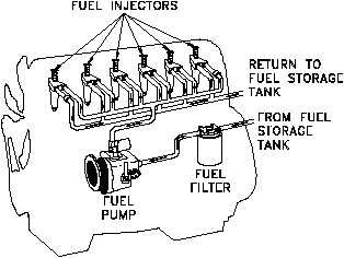
The fuel system must, therefore,
Figure 13 Diesel Engine Fuel Flowpath
not only deliver the fuel but also
ensure its cleanliness.
This is
usually accomplished through a
series
of
in-line
filters.
Commonly, the fuel will be
filtered once outside the engine
and then the fuel will pass through
at least one more filter internal to
the engine, usually located in the
fuel line at each fuel injector.
In a diesel engine, the fuel system
is much more complex than the
fuel system on a simple gasoline
engine because the fuel serves two
purposes.
One purpose is
obviously to supply the fuel to run the engine; the other is to act as a coolant to the
injectors. To meet this second purpose, diesel fuel is kept continuously flowing through
the engine's fuel system at a flow rate much higher than required to simply run the
engine, an example of a fuel flowpath is shown in Figure 13. The excess fuel is routed
back to the fuel pump or the fuel storage tank depending on the application.
ME-01
Rev. 0
Page 14


