Basic DC Theory
DC CIRCUIT TERMINOLOGY
Parallel Circuit
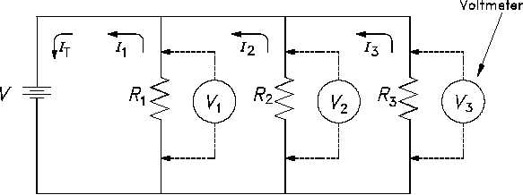
Parallel circuits are those circuits which have two or more components connected across the
same voltage source (Figure 17). Resistors R1, R2, and R3 are in parallel with each other and the
source. Each parallel path is a branch with its own individual current. When the current leaves
the source V, part I1 of IT will flow through R1; part I2 will flow through R2; and part I3 will flow
through R3. Current through each branch can be different; however, voltage throughout the
circuit will be equal.
V = V1 = V2 = V3.
Figure 17 Parallel Circuit
Equivalent Resistance
In a parallel circuit, the total resistance of the resistors in parallel is referred to as equivalent
resistance. This can be described as the total circuit resistance as seen by the voltage source.
In all cases, the equivalent resistance will be less than any of the individual parallel circuit
resistors. Using Ohm’s Law, equivalent resistance (REQ) can be found by dividing the source
voltage (V) by the total circuit current (IT), as shown in Figure 17.
REQ
V
It
Rev. 0
Page 21
ES-02


