INDUCTANCE
DC Circuits
This is an example of Faraday’s Law, which states that a voltage is induced in a conductor when
that conductor is moved through a magnetic field, or when the magnetic field moves past the
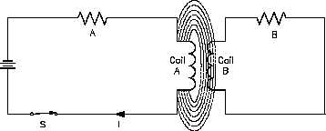
conductor. When the EMF is induced in Wire B, a current will flow whose magnetic field
opposes the change in the magnetic field that produced it.
For this reason, an induced EMF is sometimes called counter EMF or CEMF. This is an
example of Lenz’s Law, which states that the induced EMF opposes the EMF that caused it.
The
three
requirements
for
Figure 2 Induced EMF in Coils
inducing an EMF are:
1.
a conductor,
2.
a magnetic field,
and
3.
relative
motion
between the two.
The faster the conductor moves, or
the faster the magnetic field
collapses or expands, the greater
the induced EMF. The induction
can also be increased by coiling
the wire in either Circuit A or Circuit B, or both, as shown in Figure 2.
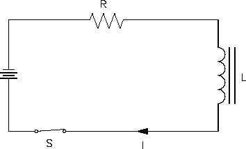
Self-induced EMF is another
Figure 3 Self-Induced EMF
phenomenon of induction.
The
circuit shown in Figure 3 contains
a coil of wire called an inductor
(L). As current flows through the
circuit, a large magnetic field is
set up around the coil. Since the
current is not changing, there is no
EMF produced. If we open the
switch, the field around the
inductor collapses. This collapsing
magnetic field produces a voltage
in the coil.
This is called
self-induced EMF.
The polarity of self-induced EMF
is given to us by Lenz’s Law.
The polarity is in the direction that opposes the change in the magnetic field that induced the
EMF. The result is that the current caused by the induced EMF tends to maintain the same
current that existed in the circuit before the switch was opened. It is commonly said that an
inductor tends to oppose a change in current flow.
ES-03
Page 2
Rev. 0