DC Circuits
INDUCTANCE
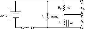
The example that follows shows how a circuit with an inductor in parallel with a resistor reacts
to changes in the circuit. Inductors have some small resistance, and this is shown schematically
as a 1W resistor (Figure 9).
1.
While the switch is closed, a
Figure 9 Inductor and Resistor in Parallel
current of 20 v/1W = 20 amps
flows through the inductor. This
causes a very large magnetic field
around the inductor.
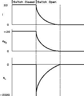
2.
When we open the switch, there is
no longer a current through the
inductor. As the magnetic field
begins to collapse, a voltage is
induced in the inductor.
The
change in applied voltage is
instantaneous; the counter EMF is
of exactly the right magnitude to
prevent the current from changing
initially. In order to maintain the
current at 20 amps flowing
through
the
inductor,
the
self-induced
voltage
in
the
inductor must be enough to push
20 amps through the 101W of
resistance.
The
CEMF
=
(101)(20) = 2020 volts.
3.
With the switch open, the circuit
looks like a series RL circuit
without a battery.
The CEMF
induced falls off, as does the
current, with a time constant TL of:
TL
L
R
.
TL
4H
101W
0.039 sec
Rev. 0
Page 7
ES-03