Electrical Distribution Systems
WIRING SCHEMES AND GROUNDING
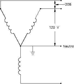
In Figure 19, an example of the Wye system, or center-grounded Wye as it is commonly referred
to, extends three current-carrying insulated conductors and an insulated grounded neutral to the
loads. Depending on the selection of conductors, one of the following is available: a reduced-
voltage single phase between a phase leg and the neutral; a full-voltage single-phase circuit
between any two phase legs; or a full-voltage three-phase power. Again, some precautions must
be taken when balancing the single-phase loads in the system. The full load ampacity of the
neutral must be sized to 1.73 times the highest phase ampacity. This is done to avoid either an
over-current condition if a fault is present or the operation of single-phase loads at reduced
voltage if the loads become severely unbalanced by accidental interruption.
Figure 19 4-Wire, Three-Phase Wye System
As with all other grounded systems, bonds are established between the grounded neutral and all
components of the system. This system is recognized as the safest possible multi-purpose
distribution system for low voltage and is commonly seen in the 208/120-volt range in many
facilities.
Summary
The important information in this chapter is summarized on the following page.
Rev. 0
Page 27
ES-15


