WIRING SCHEMES AND GROUNDING
Electrical Distribution Systems
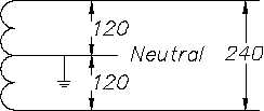
Figure 16 3-Wire Edison Scheme
The physical connections to the transformer secondary involve two insulated conductors and one
bare conductor. If the conductor is a current-carrying leg or neutral leg, the conductor will be
insulated. The remaining uninsulated conductor will serve as a safety ground and will be bonded
to the ground point of the system. In all cases, 3 wires will be presented to the load terminals,
and the safety ground will be bonded to each junction box, or device, in the distribution system.
In the case of half voltage (120 V) use, the intended path of the current is from the supply leg
through the load and back to the source on the neutral leg. No current would be carried on the
ground unless a fault occurred in the system, in which case the current would flow safely to
ground.
In the full voltage system (240 V), the insulated conductors are connected across the full winding
of the transformer, and the uninsulated conductor is again bonded to the grounded center tap.
In a balanced system, all currents will flow on the insulated conductors, and the grounded neutral
will carry no current, acting only in a ground capacity. In the case of either an unbalanced load
or a fault in the system, the bare conductor will carry current, but the potential will remain at
zero volts because it is tied to the ground point. As in the case of the half voltage system, the
uninsulated conductor will be bonded to each device in the system for safety.
Three-Phase Wiring Schemes
Unlike the single-phase wiring scheme that must make a provision for a neutral leg and separate
ground, the three-phase system needs neither a separate neutral nor a ground to operate safely.
However, to prevent any unsafe condition, all 3- and 4-wire, three-phase systems can include an
effective ground path. As with the previous single-phase discussion, only the secondary side of
the transformer and its connected load need to be studied.
3-Wire, Three-Phase Delta System
The simplest three-phase system is the 3-wire Delta configuration, normally used for transmission
of power in the intermediate voltage class from approximately 15,000 volts to 600 volts. The
diagram in Figure 17 depicts the two methods of connecting the Delta secondary.
ES-15
Page 24
Rev. 0