OTHER ELECTRICAL MEASURING DEVICES
Test Instruments & Measuring Devices
Synchroscope
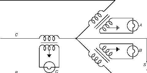
Figure 16 Ground Detector Lamp Circuit
A synchroscope indicates when two AC generators are in the correct phase relation for
connecting in parallel and shows whether the incoming generator is running faster or slower than
the on-line generator. The synchroscope consists of a two-phase stator. The two stator windings
are at right angles to one another, and by means of a phase-splitting network, the current in one
phase leads the current of the other phase by 90°, thereby generating a rotating magnetic field.
The stator windings are connected to the incoming generator, and a polarizing coil is connected
to the running generator.
The rotating element is unrestrained and is free to rotate through 360°. It consists of two iron
vanes mounted in opposite directions on a shaft, one at the top and one at the bottom, and
magnetized by the polarizing coil.
If the frequencies of the incoming and running generators are different, the synchroscope will
rotate at a speed corresponding to the difference. It is designed so that if incoming frequency
is higher than running frequency, it will rotate in the clockwise direction; if incoming frequency
is less than running frequency, it will rotate in the counterclockwise direction. When the
synchroscope indicates 0o phase difference, the pointer is at the "12 o’clock" position and the two
AC generators are in phase.
ES-14
Page 26
Rev. 0


