Test Instruments & Measuring Devices
TEST EQUIPMENT
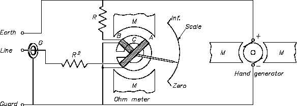
Figure 17 Simple Megger Circuit Diagram
Coil A is wound in a manner to produce a clockwise torque on the moving element. With the
terminals marked "line" and "earth" shorted, giving a zero resistance, the current flow through
the Coil A is sufficient to produce enough torque to overcome the torque of Coil B. The pointer
then moves to the extreme clockwise position, which is marked as zero resistance. Resistance
(R1) will protect Coil A from excessive current flow in this condition.
When an unknown resistance is connected across the test terminals, line and earth, the opposing
torques of Coils A and B balance each other so that the instrument pointer comes to rest at some
point on the scale. The scale is calibrated such that the pointer directly indicates the value of
resistance being measured.
Rev. 0
Page 29
ES-14

