DENSITY COMPENSATION
Level Detectors
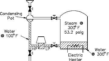
Figure 12 illustrates a vessel in which the water is at saturated boiling conditions.
Figure 12 Effects of Fluid Density
A condensing pot at the top of the reference leg is incorporated to condense the steam and
maintain the reference leg filled. As previously stated, the effect of the steam vapor pressure is
cancelled at the DP transmitter due to the fact that this pressure is equally applied to both the low
and high pressure sides of the transmitter. The differential pressure to the transmitter is due only
to hydrostatic head pressure, as stated in Equation 3-3.
Hydrostatic Head Pressure = Density x Height
(3-3)
Reference Leg Temperature Considerations
When the level to be measured is in a pressurized tank at elevated temperatures, a number of
additional consequences must be considered. As the temperature of the fluid in the tank is
increased, the density of the fluid decreases. As the fluid’s density decreases, the fluid expands,
occupying more volume. Even though the density is less, the mass of the fluid in the tank is the
same. The problem encountered is that, as the fluid in the tank is heated and cooled, the density
of the fluid changes, but the reference leg density remains relatively constant, which causes the
indicated level to remain constant. The density of the fluid in the reference leg is dependent
upon the ambient temperature of the room in which the tank is located; therefore, it is relatively
constant and independent of tank temperature. If the fluid in the tank changes temperature, and
therefore density, some means of density compensation must be incorporated in order to have an
accurate indication of tank level. This is the problem encountered when measuring pressurizer
water level or steam generator water level in pressurized water reactors, and when measuring
reactor vessel water level in boiling water reactors.
IC-03
Page 12
Rev. 0


