POWER RANGE NUCLEAR INSTRUMENTATION
Radiation Detectors
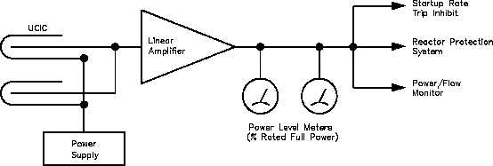
Figure 37 shows a typical power range channel.
Figure 37 Power Range Channel
Two detectors in each channel are functionally connected in parallel so that the measured signal
is the sum of the two detectors. This output drives a linear amplifier which amplifies the signal
to a useful level.
The reactor protective interface provides signals for protective actions. Examples of protective
action signals provided by the power range include:
A signal to the reactor protection system at a selected value (normally 10% reactor
power) to disable the high startup rate reactor trip
A signal to protective systems when reactor power level exceeds predetermined
values
A signal for use in the reactor control system
A signal to the power-to-flow circuit
IC-06
Page 70
Rev. 0