DOE-HDBK-1016/1-93
Engineering Fluid Diagrams and Prints
ENGINEERING FLUIDS DIAGRAMS AND PRINTS
Examples of Simple Instrument Loops
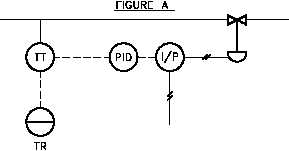
Figure 14 shows two examples of
Figure 14 Instrumentation System Examples
simple instrument loops. Figure 14
(A) shows a temperature transmitter
(TT), which generates two electrical
signals. One signal goes to a board-
mounted temperature recorder (TR) for
display. The second signal is sent to
a proportional-integral-derivative (PID)
controller, the output of which is sent
to a current-to-pneumatic modifier
(I/P). In the I/P modifier, the electric
signal is converted into a pneumatic
signal, commonly 3 psi to 15 psi,
which in turn operates the valve. The
function of the complete loop is to
modify flow based on process fluid
temperature. Note that there is not
enough information to determine how
flow and temperature are related and
what the setpoint is, but in some
instances the setpoint is stated on a
P&ID.
Knowing the setpoint and
purpose of the system will usually be
sufficient to allow the operation of the
instrument loop to be determined.
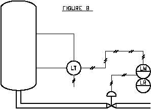
The pneumatic level transmitter (LT) illustrated in Figure 14 (B) senses tank level. The output
of the level transmitter is pneumatic and is routed to a board-mounted level modifier (LM). The
level modifier conditions the signal (possibly boosts or mathematically modifies the signal) and
uses the modified signal for two purposes. The modifier drives a board-mounted recorder (LR)
for indication, and it sends a modified pneumatic signal to the diaphragm-operated level control
valve. Notice that insufficient information exists to determine the relationship between sensed
tank level and valve operation.
Components
Within every fluid system there are major components such as pumps, tanks, heat exchangers,
and fans. Figure 15 shows the engineering symbols for the most common major components.
Rev. 0
PR-02
Page 13