READING ENGINEERING P&IDs
DOE-HDBK-1016/1-93
Engineering Fluid Diagrams and Prints
READING ENGINEERING P&IDs
Standards and conventions have been developed to provide consistency from
drawing to drawing. To accurately interpret a drawing, these standards and
conventions must be understood.
EO 1.9
STATE how the following valve conditions are depicted on an
engineering P&ID drawing:
a.
Open valve
b.
Closed valve
c.
Throttled valve
d.
Combination valves
(3- or 4- way valve)
e.
Locked-closed valve
f.
Locked-open valve
g.
Fail-open valves
h.
Fail-closed valve
i.
Fail-as-is valve
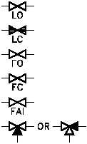
Standards and Conventions for Valve Status
Before a diagram or print can be
Figure 17 Valve Status Symbols
properly read and understood, the
basic conventions used by P&IDs
to denote valve positions and
failure modes must be understood.
The reader must be able to
determine the valve position, know
if this position is normal, know
how the valve will fail, and in
some cases know if the valve is
normally locked in that position.
Figure 17 illustrates the symbols
used to indicate valve status.
Unless otherwise stated, P&IDs
indicate valves in their "normal"
position.
This
is
usually
interpreted as the normal or
primary flowpath for the system.
An exception is safety systems,
which are normally shown in their
standby or non-accident condition.
3-way valves are sometimes drawn in the position that they will fail to instead of always being
drawn in their "normal" position. This will either be defined as the standard by the system of
drawings or noted in some manner on the individual drawings.
PR-02
Rev. 0
Page 16