DOE-HDBK-1016/2-93
ELECTRONIC DIAGRAMS, PRINTS, AND SCHEMATICS
Electronic Diagrams and Schematics
PR-04
Page 10
Rev. 0
Figure 9 PNP Transistor
Figure 10 Diode
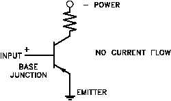
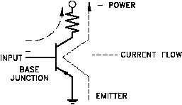
Figure 9 uses a PNP transistor. The same rules apply as above except that this time polarities of
power must change to allow current flow.
The same rules that apply to transistors hold true with diodes. However, diodes are simpler than
transistors because they have only one junction and conduct in only one direction, as indicated
in Figure 10. The diode symbol, like the transistor symbol, shows the direction of conduction by
the direction of the arrow, which is from positive to negative.
Although these simple rules will not allow you to read all electronic schematics, they will aid in
understanding some of the basic concepts.


