SECONDARY
PRIMARY
DOE-HDBK-1016/2-93
Electronic Diagrams and Schematics
ELECTRONIC DIAGRAMS, PRINTS, AND SCHEMATICS
Rev. 0
Page 7
PR-04
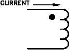
Figure 5 Transformer Polarity Markings
Reading Electronic Prints, Diagrams and Schematics
To properly read prints and schematics, the reader must identify the condition of the components
shown and also follow the events that occur as the circuit functions. As with electrical systems,
the relays and contacts shown are always in the de-energized condition. Modern electronic
systems usually contain few, if any, relays or contacts, so these will normally play a minor role.
Electronic schematics are more difficult to read than electrical schematics, especially when solid
state devices are used (The Electronic Science Fundamental Handbook discusses electrical
schematics in detail). Knowledge of the workings of these devices is necessary to determine
current flow. In this section, only the basics will be covered to assist in reading skills.
The first observation in dealing with a detailed electronic schematic is the source and polarity of
power. Generally, power will be shown one of two ways, either as an input transformer, or as
a numerical value. When power is supplied by a transformer, polarity marks will aid in
determining current flow. In this convention, dots on the primary and secondary indicate current
flow into the primary and out of the secondary at a given instant of time. In Figure 5, the current
is into the top of the primary and out of the bottom of the secondary.
Generally, the electrical power source is indicated at the point where it enters a particular
schematic. These values are stated numerically with polarity assigned (+15 volts, -15 volts).
These markings are usually at the top and bottom of schematics, but not always. In the example
shown in Figure 6, power is shown at both the top and bottom in a circuit using two power
sources. Unless specified as an Alternating Current (AC) power source, the voltages can
normally be assumed to be Direct Current (DC).


