ENGINEERING LOGIC DIAGRAMS
DOE-HDBK-1016/2-93
Logic Diagrams
PR-05
Page 6
Rev. 0
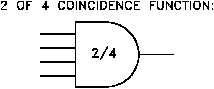
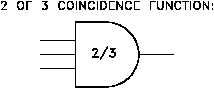
Figure 5 COINCIDENCE Gate
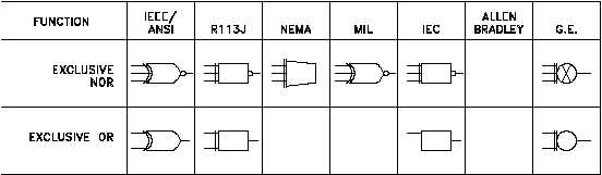
Figure 6 EXCLUSIVE OR and EXCLUSIVE NOR Gates
The COINCIDENCE gate behaves like an AND gate
except that only a specific number of the total number
of inputs needs to be on for the gate's output to be on.
The symbol for a COINCIDENCE gate is shown in
Figure 5. The fraction in the logic symbol indicates that
the AND gate is a COINCIDENCE gate. The
numerator of the fraction indicates the number of inputs
that must be on for the gate to be on. The denominator
states the total number of inputs to the gate.
Two variations of the OR gate are the EXCLUSIVE
OR and its opposite, the EXCLUSIVE NOR. The
EXCLUSIVE OR and the EXCLUSIVE NOR are
symbolized by adding a line on the back of the standard
OR or NOR gate's symbol, as illustrated in Figure 6.
EXCLUSIVE OR - provides an output (on) when only one of the inputs is on. Any
other combination results in no output (off).
EXCLUSIVE NOR - is the opposite (NOT) of an EXCLUSIVE OR gate's output. It
provides an output only when all inputs are on or when all inputs are off.
Time Delays
When logic diagrams are used to represent start/stop/operate circuits, the diagrams must also
be able to symbolize the various timing devices found in the actual circuits. There are three
major types of timers. They are 1) the Type-One Time Delay Device, 2) the Type-Two Time
Delay Device, and 3) The Type-Three Time Delay Device.