Thermodynamics
SECOND LAW OF THERMODYNAMICS
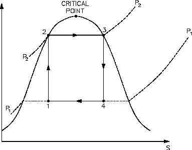
Figure 29 is a typical power cycle employed by a fossil fuel plant. The working fluid is water,
which places certain restrictions on the cycle. If we wish to limit ourselves to operation at or
below 2000 psia, it is readily apparent that constant heat addition at our maximum temperature
of 1962°R is not possible (Figure 29, 2’ to 4). In reality, the nature of water and certain
elements of the process controls require us to add heat in a constant pressure process instead
(Figure 29, 1-2-3-4). Because of this, the average temperature at which we are adding heat is
far below the maximum allowable material temperature.
As can be seen, the actual available energy (area under the 1-2-3-4 curve, Figure 29) is less than
half of what is available from the ideal Carnot cycle (area under 1-2’-4 curve, Figure 29)
operating between the same two temperatures. Typical thermal efficiencies for fossil plants are
on the order of 40% while nuclear plants have efficiencies of the order of 31%. Note that these
numbers are less than 1/2 of the maximum thermal efficiency of the ideal Carnot cycle calculated
earlier.
Figure 30 shows a proposed Carnot steam cycle superimposed on a T-s diagram. As shown, it
has several problems which make it undesirable as a practical power cycle. First a great deal of
pump work is required to compress a two phase mixture of water and steam from point 1 to the
saturated liquid state at point 2. Second, this same isentropic compression will probably result
in some pump cavitation in the feed system. Finally, a condenser designed to produce a two-
phase mixture at the outlet (point 1) would pose technical problems.
Figure 30 Ideal Carnot Cycle
Rev. 0
Page 87
HT-01