Pumps
DOE-HDBK-1018/1-93
POSITIVE DISPLACEMENT PUMPS
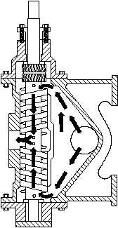
The complete assembly and the usual flow
Figure 17 Two-Screw, Low-Pitch, Screw Pump
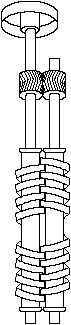
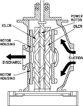
Figure 18 Three-Screw, High-Pitch, Screw Pump
path are shown in Figure 17.
Liquid is
trapped at the outer end of each pair of
screws. As the first space between the screw
threads rotates away from the opposite screw,
a one-turn, spiral-shaped quantity of liquid is
enclosed when the end of the screw again
meshes with the opposite screw.
As the
screw continues to rotate, the entrapped spiral
turns of liquid slide along the cylinder toward
the center discharge space while the next slug
is being entrapped. Each screw functions
similarly, and each pair of screws discharges
an equal quantity of liquid in opposed streams
toward the center, thus eliminating hydraulic
thrust.
The removal of liquid from the
suction end by the screws produces a
reduction in pressure, which draws liquid
through the suction line.
Three-Screw, High-Pitch, Screw Pump
The three-screw, high-pitch, screw pump,
shown in Figure 18, has many of the same
elements as the two-screw, low-pitch, screw
pump, and their operations are similar.
Three screws, oppositely threaded on each
end, are employed. They rotate in a triple
cylinder, the two outer bores of which
overlap the center bore. The pitch of the
screws is much higher than in the low pitch
screw pump; therefore, the center screw, or
power rotor, is used to drive the two outer
idler rotors directly without external timing
gears. Pedestal bearings at the base support
the weight of the rotors and maintain their
axial position.
The liquid being pumped
enters the suction opening, flows through
passages around the rotor housing, and
through the screws from each end, in opposed
streams, toward the center discharge. This
eliminates unbalanced hydraulic thrust. The
screw pump is used for pumping viscous
fluids, usually lubricating, hydraulic, or fuel
oil.
Rev. 0
ME-03
Page 25