Fluid Flow
CENTRIFUGAL PUMPS
The system has a flow rate equal to
and a total system head loss equal to DPo. In order to
Vo
maintain the flow rate
, the pump head must be equal to DPo. In the system described by
(
Vo)
the system curve (hL1), a valve has been opened in the system to reduce the system’s resistance
to flow. For this system, the pump maintains a large flow rate
at a smaller pump head
(
V1)
(DP1).
System Use of Multiple Centrifugal Pumps
A typical centrifugal pump has a relatively low number of moving parts and can be easily
adapted to a variety of prime movers. These prime movers include AC and DC electric motors,
diesel engines, steam turbines, and air motors. Centrifugal pumps are typically small in size and
can usually be built for a relatively low cost. In addition, centrifugal pumps provide a high
volumetric flow rate with a relatively low pressure.
In order to increase the volumetric flow rate in a system or to compensate for large flow
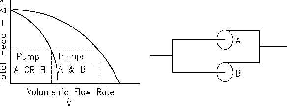
resistances, centrifugal pumps are often used in parallel or in series. Figure 11 depicts two
identical centrifugal pumps operating at the same speed in parallel.
Centrifugal Pumps in Parallel
Figure 11 Pump Characteristic Curve for Two Identical Centrifugal Pumps Used in Parallel
Since the inlet and the outlet of each pump shown in Figure 11 are at identical points in the
system, each pump must produce the same pump head. The total flow rate in the system,
however, is the sum of the individual flow rates for each pump.
Rev. 0
Page 53
HT-03